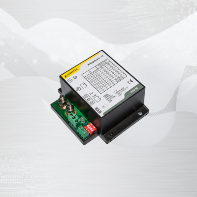
Voltage guard
The voltage guard, whose main role is to protect a battery against a deep discharge (or a bank of batteries = group), is to be connected in series between the positive pole of the bank of batteries and the uses.
You can preset a low battery voltage threshold via a combination of external microswitches.
As soon as this threshold is reached the voltage guard will offload the uses (100% of them without the possibility of making a selection except that some of them are connected directly to the batteries).
The voltage guard will automatically reconnect the uses as soon as the battery voltage increases (hysteresis).
The remote switch is used to manually control the opening of the Voltage guard.
When the remote switch is closed, the Voltage guard is open (no output voltage).
The remote LED is used to remotely view the operating state of the Voltage guard (copy of the LED present on the Voltage guard).
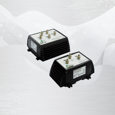
Battery isolators
It is the source – or sources – which sizes the choice of the battery isolator
I.e. RCE/100-1E-2IG model is designed for an input of 100A max.
The role of the isolator is to isolate the batteries between them and to distribute the available charging current.
The charge regulation will be ensured by the alternator (regulator) and the prioritization will be done automatically according to the state of charge of the batteries.
The nominal current of the isolator is understood on the basis of a distribution over 2 or 3 outputs depending on the model.
In the event that this nominal current is always constant on a single output (i.e. Lithium battery), an oversizing of the distributor model may be considered (consult us).
We recommend installing the battery isolator vertically as close as possible to the batteries.
The power supply must be switched off during installation.
The input terminal must be connected to the output of the alternator or the DC source concerned (solar panels, wind turbines, chargers).
The output terminals must be connected to the positive of the battery banks.
The negative of the isolator must be connected to the common negative of the batteries (on FASTON terminal – use a 0.5mm² cable – note: if this terminal is not connected, there is a major risk of destruction of the distributor).
(Reminder: all the batteries connected to the isolator must have a common negative).
The sizing of the input and output cables must be made according to the source current (rule to apply: between 3 and 4 Amps per mm² depending on the distance).
Example: for an 80A alternator and 2 batteries, RCE/100-1E-2IG model is recommended.
The input and output cables must be sized at 20mm² (80A / 4 = 20mm²). For the diameter of the eyebolts, refer to the data sheet of the isolators.
The IG terminal is an input that can be used to start modern electronically regulated alternators, even some solar or wind type regulators.
When powered, it brings a voltage back to the B + input of the isolator and therefore to the output of the source in order to excite it:
- If the alternator1 or any other source² requires a self-excitation voltage on its power output to start and regulate, then the IG terminal of the isolator must be connected
- If the alternator or any other source already has an independent terminal intended for a self-excitation voltage, then it is not necessary to connect the IG terminal of the isolator.
1 In this case, the IG terminal must be connected to the battery voltage coming from the ignition key.
2 In this case, the IG terminal must be connected to the positive pole of one of the batteries.
This IG terminal is not available on the 2-input model: RCE/100-2E-3. If necessary, it is possible to connect one or more isolator kits – see section below.
RCE/100-2E-3 model is suitable for an installation with 2 direct current sources, the sum of which must not exceed 100A (eg alternator current + solar panel).
If your installation exceeds 100A, consider using two separate RCE/100-1E-3IG isolators.
You can connect 2 sources in parallel on a single input of the battery isolator. For example: 1 alternator and 1 solar regulator on RCE/100-1E-3IG model.
But :
1 / You will need to make sure that the two devices each have an internal anti-reverse diode to prevent current from flowing between them.
2 / The total current of the two devices must not exceed the nominal current of the distributor (100A in the above case)
There is no problem connecting batteries of different capacities.
The role of the battery isolator is to share the current available at the input, on its outputs.
Prioritization will naturally occur towards the output which requires the most current.
The remaining current is then shared on the other two outputs according to the same principle.
Regulation is provided by the regulators of the DC sources present at the input.
The isolator kit, which is an optional part, may be needed if the input DC source(s) need a voltage reference to begin regulating.
For models with IG terminal and 2 sources in parallel connected to the input and both requiring a voltage reference:
In this case, the IG terminal will be used for one source and it will be necessary to add an isolator kit for the other source.
For the model without IG terminal (RCE / 100-2E-3):
It is possible to use one or 2 isolator kits as needed
Installation diagram RCE-2E-3 with a kit, an alternator and a wind turbine
Installation drawing RCE-2E-3 with a kit, an alternator and a solar panel
The green LED is on when a voltage is present on the input of the isolator and/or when the IG terminal is supplied.
The green LED will be on under the 2 conditions above if the negative terminal of the isolator has been correctly connected.
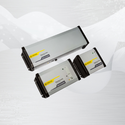
Inverters
SOLO inverters convert DC voltage from the batteries into a pure sine AC voltage of 230VAC / 50Hz.
The quality of the signal makes it possible to power all equipments even sensitive.
The rated power rating is constant, without loss, up to 45 ° C.
The overload characteristics are very important, which makes it easy to switch on all the transient starting phases of 230VAC equipment: microwave oven, hairdryer, coffee machine, fridge, refrigerator, air conditioning heating, etc.
The electronic card has a tropicalized and fungicidal varnish to resist in marine environment.
All models come with a 2 year manufacturer warranty.
Yes, you can. All SOLO sine wave inverters can easily and safely supply a computer. In fact the output voltage from an inverter is often better than that from the electricity grid.
Yes. You can connect any model of microwave to your inverter, but keep in mind that a 800 watt microwave consumes 1200 to 1300 watt from the 230V system, so you must make sure you choose the correct size inverter.
As a rule, the minimum battery capacity for a 12V installation is about 20% of the inverter capacity. For a 24V installation this would be 10%.
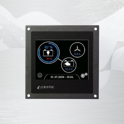
Battery monitor
Its screen, graphic and color, 3.5 inches in size, will allow you to read, in real time, the ampere-hours, produced and consumed.
In the form of a gauge, you will have, in particular, the remaining capacity of your battery (expressed, as desired, in Ah or in%).
You will be able to configure a low capacity alert threshold.
Here is the information about our battery manager, the BAT-MON-3.5:
- It consumes 100mA at full brightness and 65mA in standby mode
- A switch reduces this consumption to 0mA if necessary
- If the screen is placed after the circuit breaker, the shunt alone consumes 45mA
It is quite possible, especially in wintering mode, to cut all consumption of our BAT-MON-3.5.
To do this, simply position one or two switches to isolate the screen and the shunt.
- Solution 1
With two switches
Note that the one placed between the screen and the battery is part of the basic supply of the BAT-MON-3.5
- Solution 2
With only 1 switch
Note that if the shunt is no longer powered, it is no longer able to retain data. In other words, there will be no history when the power is turned back on.
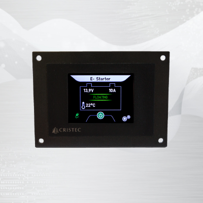
Displays for battery chargers
The UNI-DISPLAY-R model is used for the following products:
- YPOWER PLUS chargers
- HPOWER chargers (replacing the HPO-DISPLAY-R display)
- YPOWER DC-DC chargers
- YPOWER MPPT Solar Charge regulator
The YPO-DISPLAY-R model is used for the following products:
- YPOWER AC-DC chargers
- YPOWER shore-power units
This is a color touch screen (2.5 ’screen) that will allow you to control in real time:
- Each of the 2 battery voltages
- The current delivered by the charger
- The charger charging phase
- The temperature of the battery bank (if the probe option selected)
- The AC network: voltage / frequency
You can also:
- Control the charger on / off
- Pre-define high voltage / low voltage alarm thresholds
- Adjust the brightness of the day and night modes
- Name the batterie
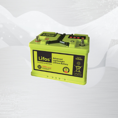
Batteries
If the first Lithium batteries were considered dangerous, those sold under the name Lithium Iron Phosphate (LiFe PO4) are much safer because of the chemical composition of their cells.
Especially since they are mostly equipped with a BMS (battery management system) which balances the cells between them while preventing overvoltage or undervoltage of the battery.
The advantages of Lithium over older generations of batteries are real.
- They are 3 times lighter than lead batteries for an identical nominal capacity.
- They are also very energy efficient, as they easily reach 100% recharge of their nominal capacity against 25 or 30% for lead batteries.
- They have a very rapid end of charge and an absorption cycle time reduced to the maximum.
Lithium batteries adapt to all your equipment on board (230V chargers, solar regulator, alternator). However, it is necessary to check the compatibility with the manufacturers of this equipment.
Another advantage, the deep discharge. Indeed, lithium batteries can be discharged to 90% while closed liquid lead batteries can only be discharged to 50%.
DC-DC battery chargers-converters
Choose my charger-converter
As a manufacturer of battery chargers, we generally recommend calibrating a charger at around 10% of the service park for Lead batteries.
Example: a 25A charger is recommended for a service park between 200 and 300Ah.
However, increasing this ratio may be justified in certain cases:
– Specific battery technology (i.e. Lithium LiFe PO4 with BMS / Recommended Ratio 30%).
– The need for additional energy to supply constant DC consumers (i.e. return from sea, short stopover, discharged batteries, you remain on the boat and a certain number of consumers are in operation): the charger must then be sufficiently powerful to recharge batteries and supply consumers.
CRISTEC chargers are compatible with Lithium Iron Phosphate (LiFePO 4) technology batteries with integrated BMS (Battery Management System).
- LiFE PO4 batteries present 3 x major advantages:
- Weight / bulk saving Autonomy thanks to the high discharge rate (90%)
- Fast charging with a suitable charging current
These are batteries that absorb a very high current when charging. It is therefore necessary to ensure, within the framework of the adaptation of an existing installation, to dimension accordingly:
- The battery charger (C / 3: example 25A model for 90Ah).
- The alternator
- Cable sections
In the case of specific Lithium batteries, please consult CRISTEC.
This option makes it possible to adapt the charging voltage of the charger according to the ambient temperature of the battery room. This allows for optimized battery charge and improves battery life. We can offer you two solutions, which can be deployed individually or be shared: Addition of an STP temperature sensor which will be connected to the charger: The latter will be placed in the battery room, as close as possible to the battery, on one of the cables, outside the box. This option is particularly recommended when the batteries are in a high temperature environment (confined room, high outside temperature, etc.).
Install my charger-converter
CRISTEC chargers can easily be installed in parallel, in order to increase their capacity.
We recommend using chargers of the same model and caliber. The length of the output cables, as well as their cross-section, must also be identical (star-shaped equipotential assembly).
The presence of LIN on certain versions (HPOWER, YPOWER DC-DC) allows totally balanced installations of master-slave type.
CRISTEC chargers are designed to be installed on a vertical wall while maintaining a 150mm area around the charger.
You have the option of installing them horizontally, but in this case IP protection will be impacted and thermal cooling will no longer be optimized.
Set my charger-converter
Our YPOWER DC-DC charger-converter is a totally adaptive product that can be configured using just 3 push-buttons.
Here is the link to our tutorial for your settings:
Note: You can exit setting mode at any time by pressing P and + for one second.
Our chargers are configured by default when leaving the factory for sealed lead batteries *.
We have worked in close collaboration with battery manufacturers to offer a charge profile that meets the needs of recharging a mixed banks: sealed lead *, AGM, gel, lead calcium and spiral lead.
* Closed electrolyte without maintenance
For certain special cases, it is possible to deactivate the Boost via the device provided for this purpose. Refer to the corresponding manual.
This function is available on the YPOWER and HPOWER ranges.
This is an automatic weekly cycle (whether or not inhibited using microswitch F) which optimizes the life of the battery.
It only intervenes after a complete recharge cycle (BOOST, ABSORPTION and FLOATING).
The charger will automatically generate a timed voltage step every 7 days regardless of the position of the Boost microswitch.
This makes it possible to limit the risks of sulphation of the plates, in particular when the service banks are composed of several elements mounted in parallel and when the latter remain permanently subjected to a floating type load regime.
Be sure to check with the battery manufacturer that this function is compatible with them (some types of AGM batteries do not support this function).
Use my charger-converter
Each charger output has a non-return device.
There is therefore no risk in starting the engine or having another charging source (solar regulator, wind turbine, etc.) which is charging with the charger running.
You can leave your CRISTEC charger connected at all times.
For long periods of inactivity, you also have the option of selecting the Wintering setting at the level of the battery type selection devices *.
* Micro-switches, encoder wheel or push button depending on model.
AC-DC battery chargers
Choose my battery charger
As a manufacturer of battery chargers, we generally recommend calibrating a charger at around 10% of the service park for Lead batteries.
Example: a 25A charger is recommended for a service park between 200 and 300Ah.
However, increasing this ratio may be justified in certain cases:
– Specific battery technology (i.e. Lithium LiFe PO4 with BMS / Recommended Ratio 30%).
– The need for additional energy to supply constant DC consumers (i.e. return from sea, short stopover, discharged batteries, you remain on the boat and a certain number of consumers are in operation): the charger must then be sufficiently powerful to recharge batteries and supply consumers.
The starter battery is not taken into account, because it is only very slightly discharged. Indeed, being naturally recharged by the alternator, the starter battery does not consume much current.
It is always preferable to dedicate a charger to batteries of the same technology.
This optimizes charging performance to 100% and therefore extends the life of the batteries.
However, the reality of the installations is often different. In our case, we supply our chargers to shipbuilding yards.
They often use Sealed Lead for the starter battery, AGM for the thruster, and now optional Lithium for service.
As such, we have worked in close collaboration with battery manufacturers, to offer a satisfactory charge profile, which allows this mix of technologies.
In this case, we advise you to keep the factory setting of the charger.
CRISTEC chargers are compatible with Lithium Iron Phosphate (LiFePO 4) technology batteries with integrated BMS (Battery Management System).
- LiFE PO4 batteries present 3 x major advantages:
- Weight / bulk saving Autonomy thanks to the high discharge rate (90%)
- Fast charging with a suitable charging current
These are batteries that absorb a very high current when charging. It is therefore necessary to ensure, within the framework of the adaptation of an existing installation, to dimension accordingly:
- The battery charger (C / 3: example 25A model for 90Ah).
- The alternator
- Cable sections
In the case of specific Lithium batteries, please consult CRISTEC.
This option makes it possible to adapt the charging voltage of the charger according to the ambient temperature of the battery room. This allows for optimized battery charge and improves battery life. We can offer you two solutions, which can be deployed individually or be shared: Addition of an STP temperature sensor which will be connected to the charger: The latter will be placed in the battery room, as close as possible to the battery, on one of the cables, outside the box. This option is particularly recommended when the batteries are in a high temperature environment (confined room, high outside temperature, etc.).
We have chosen to market separate functions: charger and converter (= inverter):
- Combis are attractive in terms of size. However, separate functions are more secure: in the event of a breakdown on a combi, you lose the AC and DC on board
- Combis often have only 2 load outputs, with one being limited in current
- The charging curves available are generally less elaborate than on a quay charger
Install my battery charger
We recommend that you install your charger as close as possible to your batteries, in order to avoid voltage drops on the DC cables.
Living spaces: CRISTEC chargers are mostly fanless, which allows you to install them in living spaces (eg berths).
For models with a fan, our remote touch screen display (YPO-DISPLAY-R offered as an option) has a night mode which allows the fan to be inhibited for 8 hours (YPOWER 12V 60A and 24V 30A models).
Engine room: CRISTEC chargers operate at full load up to a temperature of 60 ° C without any loss. On the other hand, our YPOWER 12V 40A model is ISO8846 certified (protection against the ignition of flammable gases), which allows you to install it in the engine area, near a tank.
If you have an engine battery and a service battery, you must connect:
- The engine battery with + BAT E (or + BAT D depending on generation)
- The service battery either on + BAT 1 or + BAT 2
- The unused positive output will remain in the air
- The negative will be common to both batteries
CRISTEC chargers can easily be installed in parallel, in order to increase their capacity.
We recommend using chargers of the same model and caliber. The length of the output cables, as well as their cross-section, must also be identical (star-shaped equipotential assembly).
The presence of LIN on certain versions (HPOWER, YPOWER DC-DC) allows totally balanced installations of master-slave type.
CRISTEC chargers are designed to be installed on a vertical wall while maintaining a 150mm area around the charger.
You have the option of installing them horizontally, but in this case IP protection will be impacted and thermal cooling will no longer be optimized.
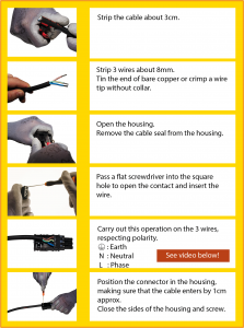
The alternative input must be made on a WAGO WINSTA type connector reference 770-103 (not supplied for OEM version).
Set my battery charger
The choice of batteries has become particularly diverse in recent years. Batteries of different technologies and components can be found on the market. It is essential to ensure that the charge profile is perfectly suited to the type of batteries.
Our chargers are equipped with devices * allowing configuration according to the type of batteries and the application. Refer to the corresponding manual.
For YPOWER or HPOWER models, it is possible to select the charging profile via the remote display option (YPO-DISPLAY-R or HPO-DISPLAY-R or UNI-DISPLAY-R).
* Micro-switches, encoder wheel or push button depending on model.
Our chargers are configured by default when leaving the factory for sealed lead batteries *.
We have worked in close collaboration with battery manufacturers to offer a charge profile that meets the needs of recharging a mixed banks: sealed lead *, AGM, gel, lead calcium and spiral lead.
* Closed electrolyte without maintenance
For certain special cases, it is possible to deactivate the Boost via the device provided for this purpose. Refer to the corresponding manual.
This function is available on the YPOWER and HPOWER ranges.
This is an automatic weekly cycle (whether or not inhibited using microswitch F) which optimizes the life of the battery.
It only intervenes after a complete recharge cycle (BOOST, ABSORPTION and FLOATING).
The charger will automatically generate a timed voltage step every 7 days regardless of the position of the Boost microswitch.
This makes it possible to limit the risks of sulphation of the plates, in particular when the service banks are composed of several elements mounted in parallel and when the latter remain permanently subjected to a floating type load regime.
Be sure to check with the battery manufacturer that this function is compatible with them (some types of AGM batteries do not support this function).
Use my battery charger
Each charger output has a non-return device.
There is therefore no risk in starting the engine or having another charging source (solar regulator, wind turbine, etc.) which is charging with the charger running.
You can leave your CRISTEC charger connected at all times.
For long periods of inactivity, you also have the option of selecting the Wintering setting at the level of the battery type selection devices *.
* Micro-switches, encoder wheel or push button depending on model.
CRISTEC battery chargers are equipped with a universal AC input (from the CPS2 range).
This system allows them to operate automatically and indifferently from all single-phase networks from 90 to 265VAC and from 47 to 65Hz.
This makes it easier to use your charger all over the world, without any intervention!